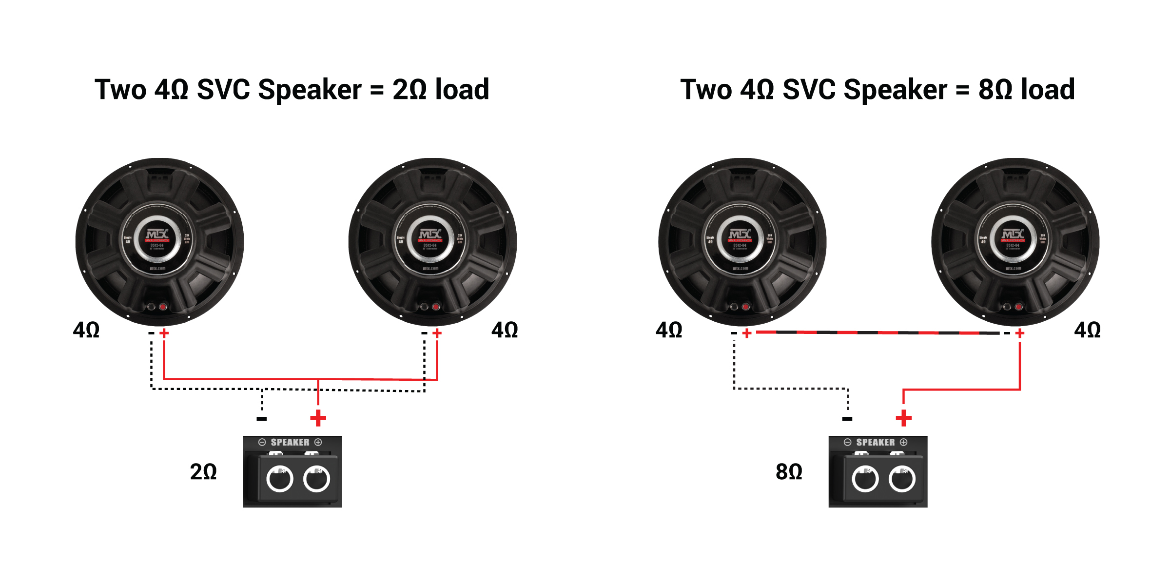
Wiring dual voice coil (DVC) subwoofers at a 4-ohm impedance requires a solid understanding of series and parallel electrical configurations to match your amplifier's capabilities safely and effectively. By choosing between series or parallel wiring, you can manipulate the final impedance load to either 2 ohms or 8 ohms, ensuring optimal power transfer, preventing amplifier distortion, and protecting your car audio system from thermal or electrical damage.
Understanding Dual Voice Coil (DVC) Subwoofers
Before diving into wiring diagrams and formulas, it is essential to understand what makes a Dual Voice Coil (DVC) subwoofer unique compared to a traditional Single Voice Coil (SVC) driver. A standard subwoofer features a single coil of wire wrapped around the voice coil former, interacting with the magnetic gap. A DVC subwoofer, however, features two independent copper or aluminum voice coils wound onto the same former.
Both coils share the same magnetic structure and cone, but they operate electrically separate from one another. This design provides audio enthusiasts with immense wiring flexibility. Instead of being locked into a single fixed impedance, a DVC subwoofer allows you to wire the two internal coils together in different combinations. This adaptability makes DVC subwoofers popular for custom car audio setups, allowing installers to match various subwoofer configurations to the stable operating range of mono-block or multi-channel amplifiers.
Voice Coil Terminology
To navigate car audio wiring successfully, you must become familiar with basic electrical metrics:
- Impedance ($Z$): Measured in ohms ($\Omega$), impedance represents the total opposition that a circuit presents to alternating current (AC) supplied by an audio amplifier.
- Resistance ($R$): While resistance refers to direct current (DC) opposition, in audio terminology, nominal impedance is typically referenced when matching speakers to amplifiers.
- Series Circuit: A wiring method where components are connected end-to-end, creating a single path for electrical current flow. Total impedance is the sum of individual impedances.
- Parallel Circuit: A wiring method where all positive terminals are connected together and all negative terminals are connected together, creating multiple paths for current. Total impedance decreases as more loads are added.
Core Electrical Principles: Series vs. Parallel Wiring
When configuring a 4-ohm DVC subwoofer—meaning each of its two internal voice coils has a nominal impedance of 4 ohms—you must apply basic rules of electrical engineering. These rules dictate how total load impedance changes based on how the positive (+) and negative (-) terminals are bridged.
Parallel Wiring Configuration
In a parallel circuit, current has multiple pathways to travel. To wire a single 4-ohm DVC subwoofer in parallel, you connect the positive terminal of coil one to the positive terminal of coil two, and likewise, you connect the negative terminal of coil one to the negative terminal of coil two.
The mathematical formula for calculating total parallel impedance ($Z_{total}$) for two equal loads ($Z_1$ and $Z_2$) is:
$$\frac{1}{Z_{total}} = \frac{1}{Z_1} + \frac{1}{Z_2}$$
For a 4-ohm DVC subwoofer with two 4-ohm coils:
$$\frac{1}{Z_{total}} = \frac{1}{4} + \frac{1}{4} = \frac{2}{4} = \frac{1}{2}$$
Inverting this fraction results in a 2-ohm final impedance. This is why this specific configuration is widely sought after; it allows a 4-ohm DVC subwoofer to present a 2-ohm load to an amplifier, which is often the sweet spot for maximizing power output on modern Class-D monoblock amplifiers.
Series Wiring Configuration
In a series circuit, current flows sequentially through one coil and then the next. To wire a single 4-ohm DVC subwoofer in series, you connect a jumper wire from the positive terminal of the amplifier (or the first connection point) to the positive terminal of coil one, connect the negative terminal of coil one to the positive terminal of coil two, and finally run the negative terminal of coil two back to the amplifier's negative output.
The formula for series impedance is simply the sum of the individual coils:
$$Z_{total} = Z_1 + Z_2$$
For a 4-ohm DVC subwoofer:
$$Z_{total} = 4,\Omega + 4,\Omega = 8,\Omega$$
Wiring a 4-ohm DVC subwoofer in series results in an 8-ohm final impedance. While this configuration runs very safely and produces exceptionally clean, low-distortion sound, it draws significantly less power from the amplifier because higher impedance restricts current flow. Consequently, series wiring for a single DVC subwoofer is rarely used in high-output car audio environments unless required by specific multi-amp bridging constraints.
Wiring Scenarios for 4-Ohm DVC Subwoofers
Depending on whether you are installing a single subwoofer or a multi-subwoofer system, your wiring choices will dictate what the amplifier "sees." Below are the primary configuration options available for 4-ohm dual voice coil drivers.
| Subwoofer Quantity | Wiring Method | Internal Coil Connection | Final Impedance Load | Typical Amplifier Compatibility |
|---|---|---|---|---|
| Single Subwoofer | Parallel | Coils wired in parallel | 2 Ohms | Most stable 2-ohm and 1-ohm monoblock amplifiers |
| Single Subwoofer | Series | Coils wired in series | 8 Ohms | Standard multi-channel amps bridged, home audio receivers |
| Dual Subwoofers | Series-Parallel | Coils in series, subs in parallel | 4 Ohms | 4-ohm stable multi-channel or monoblock amplifiers |
| Dual Subwoofers | Parallel-Parallel | All coils wired in parallel | 1 Ohm | High-end 1-ohm stable Class-D amplifiers |
The Dual Subwoofer Dynamic
If you decide to install two 4-ohm DVC subwoofers, your wiring flexibility expands dramatically. By combining series and parallel techniques across multiple drivers (often called a series-parallel network), you can achieve balanced loads that match specific amplifier thresholds. For example, wiring two 4-ohm DVC subwoofers with their internal coils in series ($8,\Omega$ per sub) and then wiring the two subwoofers together in parallel results in a final load of 4 ohms. This is an ideal target for traditional 2-channel amplifiers running in bridged mode or older multi-channel setups.
Step-by-Step Guide: How to Wire a 4-Ohm DVC Subwoofer
Executing a clean, reliable wiring installation prevents electrical shorts, phase cancellation, and premature hardware failure. Follow these structured steps to wire your subwoofer correctly.
Step 1: Gather Tools and Materials
- Digital Multimeter (DMM): Essential for verifying final impedance before connecting the subwoofer to your amplifier.
- Speaker Wire: 12-gauge to 14-gauge oxygen-free copper (OFC) wire is recommended for optimal current transfer.
- Wire Strippers and Crimpers: For prepping wire ends cleanly.
- Terminal Connectors: Spade connectors, ring terminals, or soldered connections depending on your subwoofer's terminal cup style (spring-loaded vs. threaded binding posts).
Step 2: Determine Your Target Impedance
Check your amplifier's specification manual. Look specifically at the continuous power rating (RMS) at different impedance levels (e.g., 500W RMS at 4 ohms, 800W RMS at 2 ohms). Since you are working with a 4-ohm DVC subwoofer, aiming for a 2-ohm parallel load is standard if your amplifier is 2-ohm stable.
Step 3: Execute the Parallel Wiring (2-Ohm Target)
- Cut a short segment of speaker wire to act as a jumper.
- Connect a piece of wire from the Positive (+) terminal of Voice Coil 1 directly to the Positive (+) terminal of Voice Coil 2.
- Connect another short jumper wire from the Negative (-) terminal of Voice Coil 1 to the Negative (-) terminal of Voice Coil 2.
- Run your main amplifier positive speaker wire to either of the positive terminals on the subwoofer.
- Run your main amplifier negative speaker wire to either of the negative terminals on the subwoofer.
Step 4: Verify Impedance with a Multimeter
Never trust a wiring job blindly. Turn your digital multimeter to the lowest resistance setting ($\Omega$). Touch the meter probes to the main positive and negative leads that will connect to the amplifier.
Because of DC resistance properties and meter lead variance, a nominal 2-ohm load will typically read around 1.6 to 1.9 ohms on a multimeter. If the reading is significantly higher, fluctuating wildly, or showing zero ohms (a dead short), inspect your wiring immediately to correct crossed polarities or stray wire strands touching adjacent terminals.
Common Mistakes and Troubleshooting
Even experienced installers occasionally run into issues when configuring multi-coil speaker systems. Avoiding these common pitfalls will save your equipment from thermal overload.
1. Mixing Up Positive and Negative Polarities
Reversing the polarity on just one voice coil of a DVC subwoofer creates a condition known as out-of-phase wiring. If Coil 1 pushes outward while Coil 2 pulls inward, the two coils fight each other mechanically. This results in severe cancellation of low frequencies (virtually zero bass), high distortion, rapid voice coil overheating, and potential mechanical damage to the spider and surround suspension. Always double-check color-coded stripes on your speaker wire.
2. Overloading Amplifier Impedance Limits
Connecting a wiring configuration that drops below your amplifier's minimum rated impedance (such as running a 1-ohm load on an amplifier rated only down to 2 ohms) causes excessive current draw. This triggers internal amplifier protection circuits, leading to thermal shutdowns, blown fuses, or permanent damage to the amplifier's output transistors.
3. Using Insufficient Wire Gauge
Low-resistance subwoofer loads demand adequate copper thickness. Using thin 18-gauge or 16-gauge wire over long runs introduces electrical resistance that robs your subwoofer of power. Stick to 12-gauge or 14-gauge wire for all subwoofer enclosure internal and external wiring.
Frequently Asked Questions
Can I wire a 4-ohm DVC subwoofer to a 1-ohm stable amplifier?
Yes, but not using a single subwoofer. A single 4-ohm DVC subwoofer can only be wired down to 2 ohms (parallel) or up to 8 ohms (series). To present a 1-ohm load to an amplifier, you would need two 4-ohm DVC subwoofers wired in a parallel-parallel configuration.
What happens if I only wire one voice coil on a DVC subwoofer?
Leaving one voice coil disconnected is strongly discouraged. While the subwoofer will produce sound, you lose half of the thermal handling capacity, alter the Thiele-Small parameters designed for the enclosure, and risk over-exceeding the mechanical limits of the moving assembly because the magnetic dampening provided by the second closed circuit is absent. Always wire both coils.
Is a 2-ohm load louder than a 4-ohm load?
In most cases, yes. Most solid-state car audio amplifiers are designed to produce more electrical power (watts RMS) at lower impedances (2 ohms vs. 4 ohms) because lower resistance permits higher current flow. However, this extra power output also demands more electrical current from your vehicle's charging system.
How do I know if my amplifier is 2-ohm stable?
Consult the owner's manual or specification sheet provided by the manufacturer. Look explicitly for ratings listed under "RMS Power at 2 Ohms." If the manufacturer explicitly states a minimum impedance rating of 4 ohms (common in home theater stereo receivers and bridgeable multi-channel car amps), do not wire your subwoofer to 2 ohms.
Recommendations for Your Installation Setup
When finalizing your audio setup, always prioritize matching your subwoofer's final wired impedance to an amplifier tier that operates comfortably within its specified thermal limits. Secure all internal enclosure wiring with zip ties or silicone adhesive to prevent vibrations from rattling connections loose over time. Test your final impedance using a digital multimeter before powering up the system, and set your amplifier gains using a calibrated method to ensure clean, clipping-free bass performance.